Observations from Big Data Analytics #wmbda

2013.01.01 [IMG_0062]

Another interesting bda from Whitehall Media. Lots of detailed information but a couple of overall observations:

Whilst it has been going on for a while it is significant how many companies formally associated mostly with hardware are moving into software and consulting: both Dell and HP talked about their big data achievements with almost no mention of the hardware. I think this is further evidence of how commoditised hardware and system software is becoming, probably being driven by cloud offerings. The real value to be gained from IT is shifting from being able to master the Technology to fully exploiting the Information.

In listening to talks about how to make big data succeed a couple of words jumped out at me: curiosity and discovery. A number of speakers talked about the need to find the right people from within your organisation who can form a team to drive the initiative and that no single person is going to be the key. They will need to have a combination of technical skill, domain knowledge and vision and be allowed to explore without fear of being labelled a failure because, even if analysis of some data does not give you actionable insights, you now know more about that data.


Architecture Archaeology

IMG_0155

Often the Architect will come across an aspect of the organisation they have not needed to tackle in the past. This could be for a number of reasons, maybe they are new to the organisation, it was part of an acquisition, or they have simply never had time to become familiar with this part of the organisation and it has not featured in any recent projects. The architect now needs to perform some architecture archaeology. My advice is to look to the following sources:

  • Existing documentation: this comes with a big health warning – it is probably wrong. Not because it was wrong when written but there have probably been changes in the meantime. If, indeed, it exists at all. If it does exist that’s a great start but it may not exist in an electronic format or in your modelling tool of choice. My advice would be to bring it into your tool of choice, copying by hand if necessary, as you are probably going to need to modify it.
  • Database: if the system(s) under investigation has a database go there next. The database is probably your best bet to understand the data entities involved and the relationships between them. Some databases will include referential integrity which is the best bet for understanding relationships but if there is none you’ll need to make some deductions based on field names. Indexes may also be a clue, as they are often created in order to tune performance for joins. Stored procedures could be useful, I’ll discuss those under ‘Code’
  • Users: will be able to demonstrate how they use the system(s) revealing its functional purpose, the workflows involved and participating data entities. But be warned, each individual user may not exercise all the functionality in the system so take a look for yourself at menus to see if all options and sub-options have been exercised. Even then there is no guarantee everything is covered as some systems reveal functionality dynamically based on user permissions and/or the content of records being processed.
  • Developers: if the original developers are still around you’re in luck
    as you should be able to work with them to get a pretty good understanding of
    the system(s). My experience is that they don’t remember to tell you everything
    so it’s worth comparing this with at least one other source and especially if
    the original developers are all gone and its being maintained by others.
  • Code: code is the ultimate authority in describing a system. I’ve bored many colleagues by repeatedly explaining that if their specification is unambiguous it can be complied. Code is the only unambiguous explanation of what a piece of software does. Now there are many coding styles and some are easier to reverse-engineer into an architectural artefact than others. If you are an Architect who does not have a development background it could be quite a tough job so get some help. Amongst the easiest style to deal with pushes virtually all the business rules logic into stored procedures which make it quite a simple exercise of looking through each stored procedure. The worst are the balls of mud which will contain multiple styles, middleware and/or languages, don’t underestimate how big a job decoding these will be.  There are tools which will help model and document the code but these will give structure rather than function and their usefulness varies greatly depending on the structure (or lack of).
  • Logs/Monitoring: can be really useful to understand the dependencies between this system and others. For example a Service Oriented Architecture relying on Web Services can easily be mapped by examining the web server log files.

By combining the results from all the above it is possible to get a complete picture however you might only need to understand one aspect, like data, so pick those that make sense.


Your Data and NOSQL: Graph Databases

2013.10.23 [IMG_0133]

I’d like to start by explaining why I referred to “NOSQL” rather than “NoSQL”: I believe that “Not Only SQL” is more accurate than “No SQL” because, of course, we can make use of both relational databases and the alternatives like document and graph. In fact this is probably just about the most miss-leading terminology of recent years because, as you will see from this article, Graph databases are structured and have query languages so they are in those regards no different to relational databases. Rant over, let me describe what I’ve learnt and hope it of help to your own journey beyond relational databases.

The reason I started working with a Graph database was to help my research into Social/Organisational Network Analysis. To get beyond the basics and start to really understand influence, and how it changes over time, I needed to be able to query the composition and strength of multiple individuals’ networks, enter the Graph Database. I won’t try explaining the concepts of a Graph Database as Wikipedia does an excellent job so I’ll jump straight in assuming you read the Wikipedia article. I chose to use Neo4j because there is some support for .NET via a couple of APIs. For the purposes of this discussion the key constructs in Neo4j are: nodes (vertices), relationships (edges) and attributes; both nodes and edges can have attributes.

The data entities I have been dealing with are: employees and items of electronic communication such as email and IM as well as other pieces of information that help identify the strength of social ties such as corporate directories, project time records and meeting room bookings. There is a whole spectrum of how these can be represented in a Graph Database but I will look at three scenarios I have either implemented, seen implemented or considered.

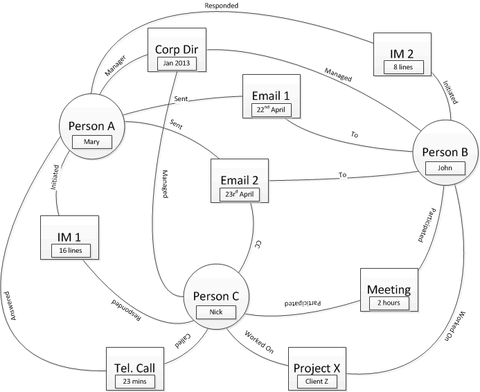
1)      Everything is a node
graph database 1

All the entities you might have previously placed in a relational database become a node, complete with all the attributes such as “meeting duration”. There are relationships between the nodes which have a type and may also have additional attributes.

Advantages: all the data in one place; you have the flexibility to query the graph in as much detail as the captured attributes allow.

Disadvantages: you could end up with a lot of nodes and relationships, the 2000 person organisation I studied produced well over a million emails per month so by the time you add in IMs and other data over a couple of years you will be in the 100 million plus range for nodes and even more for relationships potentially giving you an actual [big data] problem as opposed to the usual big [data problem]; the queries could be very complex to construct, perhaps not an issue once you have some experience but it might be better to start with something simpler.

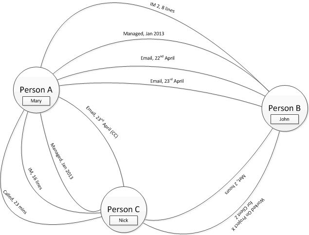
2)      Most things are a relationship
graph database 2

Here we keep only the ‘real world’ entities, the people, as nodes and push all the other information into relationships. For my study this would massively reduce the number of nodes but not relationships. In fact for some information, like attendance of a given meeting, the number of edges dramatically increases from n (where n is the number of people in the meeting) to n(n − 1)/2 (a complete graph).

Advantages: a lot fewer nodes (depending on the characteristics of the information involved)

Disadvantages: more edges (depending on the characteristics of the information involved); duplication of attribute information (e.g. meeting duration) in relationships; might make some queries harder or not possible.

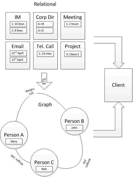
3)      Hybrid Relational-Graph
graph database 3

This approach effectively uses the Graph Database as a smart index to the relational data. It was ideal for my Social Network Analysis because I only needed to know the strength of relationship between the people(nodes) so was able to leverage the power of the relational database to generate these using the usual ‘group by’ clauses. I’ve shown an ETL from the Relational data to the Graph data because that’s the flow I used but they could be bi-directional or built in parallel.

Advantages: much smaller graph (depending on the characteristics of the information involved), in my data sets I’ve found 1,000 employees mean around 100,000 relationships; much simpler graph queries.

Disadvantages: Data in two places, which needs to be joined and risks synchronisation problems.

As you can guess I like the third option, mostly because it’s a gentler introduction in terms of simplicity and scale, you are less likely to write queries which attempt to return millions of paths!

At the beginning (in the rant section) I mentioned Neo4j has a query language (actually it has two). Rather than repeat myself take a look at my Data Science blog where I describe some Cypher queries.

Cloud: initial evaluation of Windows Azure PaaS

2013.01.11 [IMG_0183]

Back in June 2013 I built an Azure architecture prototype that collected Twitter data, stored it, analysed it and presented the results through a web interface. It’s been running now for a number of months, not needing any attention and doing a great job. Now as every experienced IT Architect knows the true test of a good architecture comes when the client needs to make some changes: that time has arrived as I’m now looking at how to implement a more sophisticated analysis of the structure of a targeted sub-graph of tweeters.

Let me explain the parts I’ve evaluated: I’ve deliberately only used Platform-as-a-Service (PaaS) components and avoided VMs, i.e. Infrastructure-as-a-Service (IaaS), because I believe PaaS will give organisations the greatest impact when adopting Cloud (but that’s another topic). The specific components from my architecture prototype are listed below.

Worker Role

Think of these like services in windows; normally they sit in a loop picking up, and responding to, tasks.  I’ve been impressed with how easy it is to create, configure and deploy worker roles although debugging has been harder. I’ve been aware that to perform more sophisticated analysis on Twitter a Graph Database would be ideal and I thought this would, inevitably, require using IaaS to install a VM. But no, I found a really fantastic example of what a worker role is capable of: it can be configured to connect to a VHD, dynamically install Java, install Java applications and then start the Java application; voila Neo4j running on a worker role! So worker roles – definitely make use of them.

Table Storage

Provides a basic mechanism to store structured data. It’s fast (once you understand how it is indexed), it appears to scale well (I’ve not pushed it that far though) and very, very low cost. However, there is a downside: Table Storage is nowhere near as flexible as a relational database, it does not support joins, you cannot add additional indexes, specify sort orders or group by clauses. None of these limitations are a problem if your requirements are straightforward and not going to change but when I look at how to get from what I’ve got to what I want it’s going to be a lot of work compared to a relational database. In conclusion look to use table storage where you want to store simple, discrete, entities, you don’t mind doing a bit of data manipulation in code (e.g. summarising, joining) and requirements change will be low. For my next Azure architecture prototype I will be using the Azures PaaS relational database: Windows Azure SQL Database.

Web Sites

Come in a number of flavours, the most basic of which is an instance in a multi-tenanted IIS server (and free!). My Websites were pretty basic: connect to Table Storage, drag back the data and display it on the webpage. Again the build, deploy and configure are all very smooth. I can’t say I really pushed Websites to the limit but I have seen other, more sophisticated, sites which seem to be just as easy to manage and perform very well.  Azure Websites: yes, use them.

Blobs

For storing files and other chunky bits of data. Have worked fine for me, no problems at all. I have no reservations in recommending their use when appropriate.

Queues

I’m talking about the storage service queues, not Service Bus. I did not use these in my architecture prototype but I have experimented with them; from what I’ve seen I think they will do a great job in the right place.

Conclusion:

Worker Roles, Web Sites, Blobs, Queues : great, use them.

Table Storage: maybe, think carefully – is it right for your problem?


When SOA makes sense

2013.05.25 [IMG_0482]

I’ve always maintained its difficult judge your Enterprise Architect at annual reviews because the success of what we do can only really be judged over longer periods. I’d like to share a SOA success story that goes back to 2005 and has stood the test of time:

The initial business problem was to outsource part of the organisation but reading between the lines it could be seen that this was an area that was likely to undergo more changes. It also involved multiple ‘consumer’ systems wanting to use similar ‘services’ that would be provided from more than one system.

The scenario met the two things I have come to recognise as requirements where a SOA will deliver the maximum impact to the organisation:

1)      There is demand from three, or more, systems for a given service. This satisfies Robert L Glass’s “rule of three” (Fact 18) from his book Facts and Fallacies of Software Engineering which states it is “three times as difficult to build reusable components as single use components” and “a reusable component should be tried in three different applications before it will be sufficiently general….”. I’ve seen SOA approaches used where there is only a single client and yes, these work, but was the extra build cost worth it?

2)      The organisation using the proposed SOA is undergoing a prolonged period of change. How you can judge this is more gut instinct than a known fact but you can look at how the wider industry is changing.

I’d say these two facts alone make SOA a likely candidate but there was a third reason: the service was likely to be provided by more than one implementation (because some of the requests would be answered by another organisation) thus a need to bring in some middleware features like content-based-routing.

Buying a service from another organisation is also a good indicator that SOA principles and designs can be applied because there must be a contract, both in the legal sense and technical sense.  I would expect the purchasing organisation to drive the integration and the supplying organisation to provide the service, technically.

So what happened? Well the SOA went in fairly smoothly and then:

  • The outsourcing was abandoned
  • A significant portion of the original systems were replaced with updated implementations
  • The organisation was sold and merged with another organisation, requiring additional ‘consumers’ and’ providers’ to be added and requests to be routed
  • The newly merged organisation sold a large part of itself, introducing even more complexity during a two-year transition
  • Once the transition was complete the remaining systems could be simplified

Throughout all these changes the SOA proved to be adaptable and flexible. Some changes were necessary but the fundamental design endured.


Capabilities: one is not the number you are looking for

IMG_0880

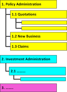
I’ve been a fan of business capability reference models (BCRM) for a while now. These are a great tool for looking at existing IT landscapes and new projects to understand the degree to which functionality is duplicated from a business perspective. A BCRM is a hierarchical breakdown of the capabilities, or functions, an organisation needs. For example a financial services organisation may include Policy Administration and Investment Administration as top-level capabilities. In turn these will break-down to lower level capabilities, e.g. Policy Administration will need to provide quotations, new business processing and claims handling. There is no limit to the number of levels but in financial services four to five seems typical.

BCRM

With the BCRM it is possible to look at each piece of software and list which capabilities it implements and then to establish where there is duplication.

So what to do when duplication is discovered? Surely an organisation only needs one piece of software supporting a given capability? Well maybe; I’ve previously described some reasons why an organisation might want to retain two systems serving similar capabilities. I would also observe that aiming for one system per capability is the correct answer if the organisation is going to remain static and has no prospects of internal or external change in the medium term. However, in a changing world, and organisations, you are quite likely to find: an older system in declining use, the current (‘strategic’) choice, and maybe something new and experimental. Perhaps tolerating  around three is a reasonable position from an EA perspective.


Simple solution for data-driven web availability

2013.05.25 [IMG_0438]

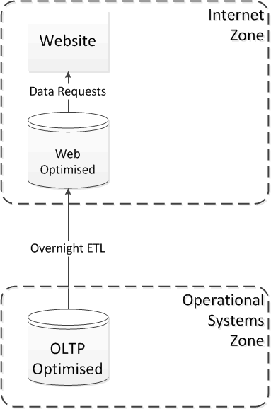
I’d like to share a simple pattern that has worked well for the past decade. For many good reasons (security, availability, performance, etc.) it is not usually a good idea to connect a website directly to operational systems, unless it is providing an e-commerce function. It’s quite a common design to have a web-optimised database refreshed overnight from operational data, as shown:

flip-flop_1

One of the disadvantages of this design is finding a solution to updating the Web database without causing downtime or inconsistencies: typically you could either drop and re-create the whole database (which can lead to unavailability) or perform a delta update (which can be very complex to implement).

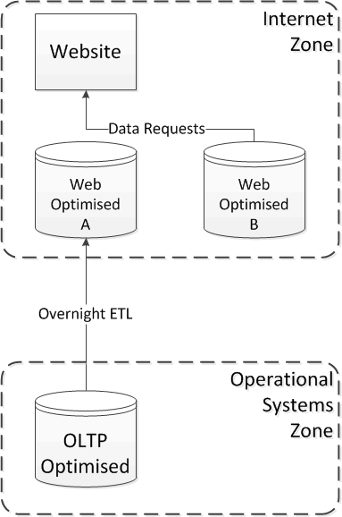
My preferred solution is to use a pair of databases and then ‘flip-flop’ between them: whilst the Website is using database A database B can safely be dropped and re-created:

flip-flop_3

Once the database is fully refreshed a flag is set which means subsequent sessions are switched to the most recently refreshed database and the next refresh will drop and re-create database A:

flip-flop_2


Migration: Beyond ETL

2013.05.26 [IMG_0514]

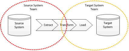
When approaching a migration it is tempting to try and do the simplest thing that could possibly work, most likely a re-key or one-off ETL , because any code or process created for the migration is probably going to be discarded once complete. Assuming a code solution is proposed then it’s probably going to look like this:

Beyond ETL 1

So who is going to do the work? If it’s a single team then maybe this approach will work but if there are two teams: one focussed on the source system and one focussed on the target system then the question is who works on what, most likely the answer is the sending system team gets to do the extract and the target system team does the load but who does the transform?

Beyond ETL 2

Working on the transform is probably going to take both teams. This has some problems:

  • both teams need to understand each-others data-model which, of course, can be very complex especially if one party forgot the most important step of normalisation.
  • codes need to be mapped and this is often not a one-to-one relationship
  • the target system team need to understand where data might be missing in the source system
  • the target system team need to understand what to do about data quality problems in the source system
  • reconciling the migration will be difficult if both data models are complex.

The answer: introduce an intermediate data model

Beyond ETL 3

The main design consideration of the intermediate data model is that it should be clear and simple to understand, there should be no ambiguity; it has the following features:

  • The structure is as simple as possible: code tables are denormalised  and merged back into the major entities; user management data can be removed along with system log or other management tables.  Both teams are likely to need to come together to agree the structure because this is the common representation of the data from both systems.
  • The structure does not need to match either the source or target system (if it does maybe you don’t need this step).
  • All codes are turned into a description, e.g. replace a status code of “1” with ”Active”
  • Column names for tables should be as descriptive as possible.
  • Optimisation for performance involving changes to structure should only be considered if absolutely essential.
  • Missing data should be explicitly marked as such.
  • Data quality issues should be resolved by the source system team as part of their ETL.

The advantages of using the intermediate data model are:

  • Each team can focus on their area of expertise
  • There is less scope for ambiguity leading to mistakes and subsequent rework
  • Reconciliation can be split into two, simpler, reconciliations (source to intermediate and intermediate to target)
  • The target system team are not bound to the source system team making data available, they should understand the intermediate model well enough to generate test data
  • The intermediate data model serves as an archive for subsequent audit or enquiries needing to understand how data was created in the target system

It is especially worth considering using an intermediate data model if the migration is split into phases, or there will be multiple source systems over time, as it can be extended and modified to represent any unique requirements at each phase, or source system, rather than having to understand all of these complexities at one time.

These advantages are also applicable to integrations that follow the ETL model.

Authenticating B2B Integrations with Tokens

2012.01.07 [IMG_8721]

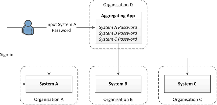
I was surprised to discover that a common practice in certain B2B integrations, in part of the financial services sector, was for user names and  passwords to be stored in consuming applications. To understand the scenario where this occurs see the diagram, below:

B2B Tokens

Here a user has access both the System A and System D. System D aggregates information from a number of systems, all of which are owned by different organisations. The user puts their password for System A into System D and this is subsequently used by System D to act on behalf of the user when requesting information, or transactions, from system D. There are a number of problems with this:

1         The password must be presented to System A as entered so it must be stored either in plain text or reversible encryption which makes it vulnerable to theft.

2         When the user has to change their password for System A they must also change it in System D; failing to do this can lead to account lock-outs

3         Organisation A may want to revoke user A’s access via Organisation D but still allow direct access, this complicates System A.

Potentially problem 1 can be resolved by hashing the password but this has its own problems: you must be very careful the hashing routines are absolutely identical – I’ve seen cases where .NET and Java implementations differ; hashes can be broken using multi-GPU hardware; and this does not address 2 or 3

The answer is to issue the user with a token instead of requiring them to use their password, much as OAuth does: this can either be done by creating a registration process between Application D and Application A or adding a UI to application A to generate the user a token. Application D then presents the token instead of a password.  The advantages are:

1         The password never needs to be stored in a reversible form (application A will salt and encrypt it)

2         The token can have a validity independent of the password (e.g. 12 months instead of 1 month)

3         Account lock-outs are avoided

4         The token can be part of a defence-in-depth approach, for example Organisation A can place an IP restriction on access from Organisation D

5         Organisation A can revoke the taken whenever is choses

6         The aggregating application (D) simply needs to store the token instead of a password so does not need to be modified unless a registration process driven through the aggregating application (D) is desired.

To summarise: in B2B integration scenarios consider tokens as part of the security solution.

Integration: let’s have a conversation

2011.12.24 [IMG_8480]

Having established who is driving the integration it’s tempting to start designing the message content or turning to a messaging standard like ORIGO or FIX.  However there is a layer above the message content that needs to be considered: conversation patterns. This is also a valid consideration for standards which often concentrate on the content and, whilst conversation patterns are implied or stated, it’s important to be certain about which you are using and the consequences of that choice.  Don’t go mad with the number of conversation patterns for the integration, try and keep it to a small set. The following are taken from a solution I designed in 2005, which has stood the test of time:

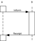
  • Inform-Receipt:

Inform-Recipt

A wants to tell B something and wants B to acknowledge it has been told; A does not need any information back from B, other than the acknowledgement.

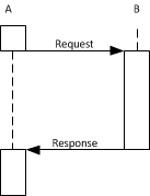
  • Request-Response:

Request-Response

A wants some information from B. ‘Ah!’ I hear you say, ‘that’s the same as Inform-Receipt!’, well you are probably going to implement them the same way but the conversation is different: in Inform-Response B is getting something from A but in Request-Response A is getting something from B. Also note that B is not bothered if A actually got the response.

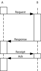
  •  Request-Response-Receipt

Request-Response-Receipt

Extends Request-Response such that B now needs to confirm A has received the response before continuing.

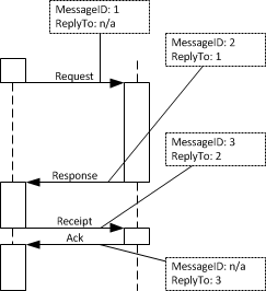
Once you have established the conversation patterns consider a scheme for giving each message a unique identifier; this is useful for debugging problems but critical for managing idempotency and allowing for re—transmission if the connection or message is lost.

Message IDs


My final observation about conversation patterns is to be very clear about persisting the message before acknowledging receipt and, if possible, do this in a transaction otherwise it becomes much harder to sort out missing and duplicate message problems.